GLOBALSAT GPS Engine Board
Hardware Data Sheet
Product No : MT-5631G
Version 0.1
Globalsat Technology Corporation
16F., No. 186, Jian-Yi Road, Chung-Ho City, Taipei
Hsien 235, Taiwan
Tel: 886-2-8226-3799 Fax: 886-2-8226-3899
Issue Date
APPR
CHECK
PREPARE
2012/11/30
Luwalk Lee
2012/11/30
- 1 -
MT-5631G
High Performance GPS Engine Board
Product Description
Product Description
MT-5631G is a compact, high performance, and low power consumption GPS+GLONASS engine
board. This GPS module is powered by MediaTek, it can provide you with superior sensitivity and
performance even in urban canyon and dense foliage environment. The miniature size makes the
module easy and the best choice to integrate into portable device like mobile phone, PDAs,
camera and vehicle locators. Automotive navigation
z Personal positioning
z Fleet management
z Mobile phone navigation
z Marine navigation
Product Features
z MediaTek high sensitivity solution
z Support 66-channel GPS
z Very high sensitivity (Tracking Sensitivity: -164 dBm)
z Extremely fast TTFF (Time To First Fix) at low signal level
z Support USB and Serial port NMEA output
z Built-in LNA
z Compact size (15.9mm * 13.1mm * 2.4mm) suitable for space-sensitive application
z One size component, easy to mount on another PCB board
z Support NMEA 0183 V3.0 (Output: GGA, GSA, GSV, RMC, VTG, GLL, ZDA)
2012/11/30
- 2 -
MT-5631G
High Performance GPS Engine Board
Product Pin Description
PIN Number(s)
Name
Type
Description
Note
1
RF IN
RF
GPS antenna input
2,3,4,6,8,9,10,12
14,15,17,19,21,
GND
P
Ground.
22,23,24,26,28,
29,33,35,36
This is the battery backup power input for
5
VBAT
P
the SRAM and RTC when main power is
removed.
7,32,34,16,25
NC
NC
This is the main power supply to the engine
11
VCC
P
board. (3.1Vdc to 3.5Vdc)
13
RESET
I
MT-5631 reset pin. This input is low active.
User can use this I/O pin for special
18
GPIO
I/O
functions. (For example, control LED)
20
TIMEMARK
O
One pulse per second output.(1PPS)
MT-5631 hardware standby function, that is
27
WAKE_UP
I
edge-trigger type, falling to enter standby
mode, and raising to normal mode
This is the main transmits channel for
outputting navigation and measurement
30
TXD
O
data to user’s navigation software or user
written software. Output TTL level.
This is the main receive channel for
31
RXD
I
receiving software commands to the engine
board from user written software.
2012/11/30
- 3 -
MT-5631G
High Performance GPS Engine Board
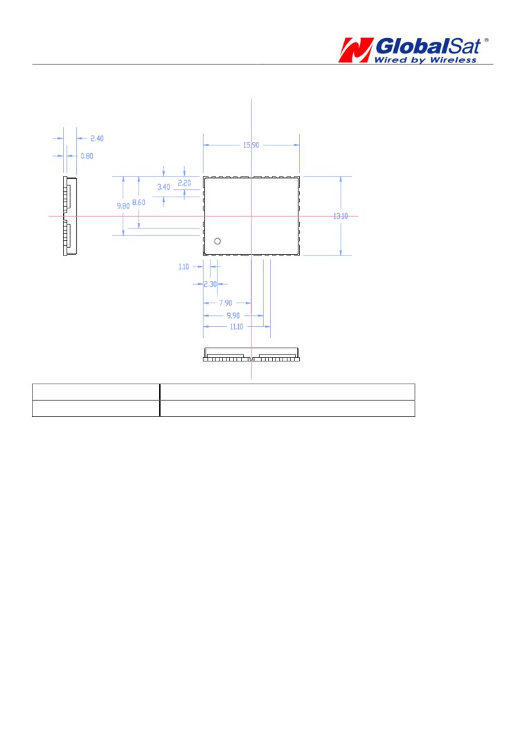
Package Dimensions
Unit: mm
Type
36-pin stamp holes
Dimensions
15.9 mm * 13.1 mm * 2.4mm ±0.2mm
2012/11/30
- 4 -
MT-5631G
High Performance GPS Engine Board
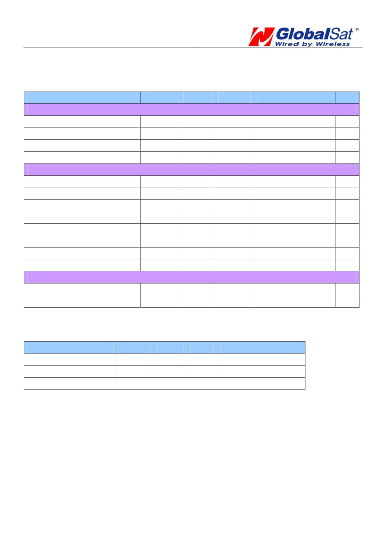
Electrical Specification
Absolute Maximums Ratings
Parameter
Min.
Typ.
Max.
Conditions
Unit
POWER Supply
Main power supply
3.1
3.3
3.5
V
Backup battery supply
2.0
3.5
V
Main power supply Current
25
mA
Backup battery supply Current
4.5
5
5.5
uA
Interface (VCC = 3.3V, VBAT= 3.3V, Operation Temp.= 25℃)
High Level input Voltage
0.7*VDD
3.5
V
Low Level input Voltage
-0.3
0.3*VDD
V
High Level input Current
10
(V=2.85V)
-10
uA
60
(with Pull Low)
Low Level input Current
10
(V=0V)
-10
uA
-60
(with Pull High)
High Level output Voltage
0.75*VDD
V
Low Level output Voltage
0.25*VDD
V
RF Input
Input Impedance
50
Ω
Operating Frequency
1.575
Ghz
☆ VDD is 2.85V for MTK CHIP
Environmental Characteristics
Parameter
Min
Typ
Max
Unit
Humidity Range
5
95
% non-condensing
Operation Temperature
-40
25
85
℃
Storage Temperature
-40
85
℃
2012/11/30
- 5 -
MT-5631G
High Performance GPS Engine Board
Receiver Performance
Tracking :
-164dBm
Sensitivity1
Autonomous acquisition :
-147 dBm
Cold Start - Autonomous
< 35s
Warm Start - Autonomous
< 35s
Time-To-First-Fix2
Hot Start - Autonomous
< 1s
Autonomous
< 3m (2D RMS)
Horizontal Position accuracy3
SBAS
< 2.0m
Speed
< 0.01 m/s
Velocity Accuracy4
Heading
< 0.01 degrees
Reacquisition
0.1 second, average
Max Update Rate
5 Hz
Maximum Altitude
< 18,000 meter
Maximum Velocity
< 515 meter/ second
Maximum Acceleration
< 4G
<Note>
1. -142 dBm ≈ 28dB-Hz with 4 dB noise figure
2. 50% -130dBm Fu 0.5ppm Tu ±2s Pu 30Km
3. 50% 24hr static, -130dBm
4. 50% @ 30m/s
2012/11/30
- 6 -
MT-5631G
High Performance GPS Engine Board
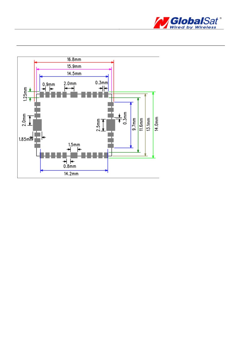
PCB Layout Recommend
Recommended Layout PAD
Unit: mm
Tolerance: 0.1mm
PCB Layout Recommendations
Do not routing the other signal or power trace under the engine board.
RF:
This pin receives signal of GPS analog via external active antenna .It has to be a controlled
impedance trace at 50ohm.
Do not place the RF traces close to the other signal path and not routing it on the top layer.
Keep the RF traces as short as possible.
Antenna:
Keep the active antenna on the top of your system and confirm the antenna radiation pattern、
axial ratio、power gain、noise figure、VSWR are correct when you Setup the antenna in your case.
2012/11/30
- 7 -
MT-5631G
High Performance GPS Engine Board
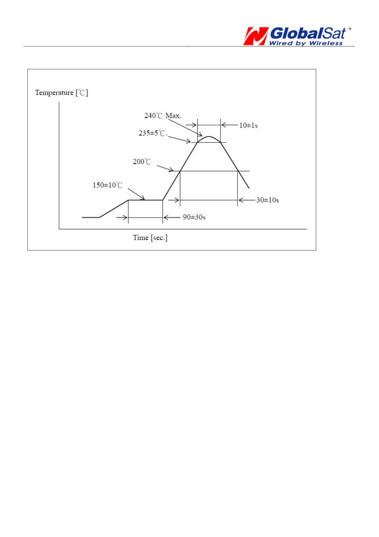
Recommended Reflow Profile:
Pre heating temperature:
150±10[℃]
Pre heating time:
90±30[sec.]
Heating temperature:
235±5[℃]
Heating time:
10±1[sec.]
Peak temperature must not exceed 240℃ and the duration of over 200℃ should be 30±10
Seconds.
2012/11/30
- 8 -